


Import and display PLC variables
Resources for this module
XML file with the PLC variables to import: download :download: here <codesysTags.xml>.
Purpose of this module
In this module, we will import variables from a CODESYS PLC to graphically display the value of a variable in the Q Application graphical interface and, in subsequent modules, configure the display of alarms and configure recipes.
To simulate the change of the variable value on the PLC, we will also configure a graphical object through which to change the value manually at runtime.
This is the result:
Import the PLC variables
To design applications that exploit the variables on the PLCs, they must be imported into the project: this can be done with a direct connection to the PLC on the network (online mode) or by importing a file of variables exported from the PLC (offline mode). For simplicity, in this tutorial we will import the variables from an XML file.
In any case, it is necessary to configure a specific driver object for the protocol of interest and a station object for each specific PLC that uses the same protocol.
We will create the objects and import the variables:
In Project, right-click the CommDrivers folder, then select New > CODESYS driver: DriverCodesys1 appears in CommDrivers. This object represents the CODESYS protocol.
Right-click DriverCodesys1, then select New > CODESYS Station: CodesysStation1 appears in DriverCodesys1. This object represents the PLC, and the connection parameters are available among its properties.
In Project, expand CodesysStation1 and click TagImporter: this is the object with which to import the variables in online or offline mode.
Set the Mode property to Offline, then in the File path property click Browse and select the codesysTags.xml file downloaded previously.
Double-click TagImporter to open its editor. All the variables present in the XML file can be displayed by expanding the nodes.
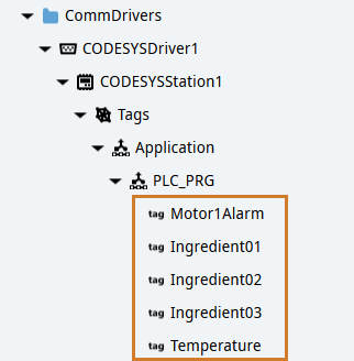
In the PLC_PRG node, select the Ingredient01, Ingredient02, Ingredient03, Motor1Alarm and Temperature variables, then click Synchronize: the variables are imported in the project, inside CodesysStation1 > Tags.
Organize the graphical objects
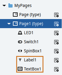
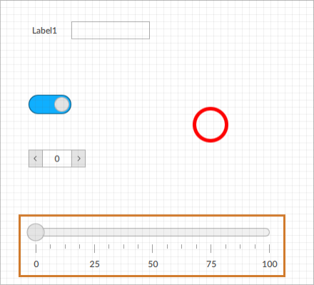
In Page1 (type), we will create a label and a text box respectively, to describe and display the value of the PLC variable. Then we will create a linear gauge with which we can simulate the change of the PLC variable value at runtime.
In Project, right-click Page1 (type), then select New > Basic controls > Label Label: Label1 appears in Page1 (type).
Repeat the procedure for the text box (Basic controls > Text box Text box).
Double-click Page1 (type) to display the panel in the editor.
Tile the two objects by dragging them. Below is an example:
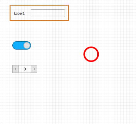
In Project, right-click Page1 (type), then select New > Basic controls > Linear gauge Linear gauge: LinearGauge1 appears in Page1 (type) and in the editor.
Position the linear gauge where you like in the editor. Below is an example:
Display the value of a PLC variable
To display the value of the imported Temperature variable, we will set a dynamic link between the Text property of TextBox1 and the value of the variable:
In Project, double-click Page1 (type) to display it in the editor.
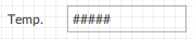
To display the Temperature variable value in the text box, drag it from Project inside the text box in the editor: a placeholder in the text box appears in the editor.
Note
in this way, we have set a dynamic link in the Text property of the text box.
To change the Label1 label text, double-click it in the editor and write some text describing the value, for example Temp..
Simulate the value change of the PLC variable
The value of the Temperature variable is static, as the PLC is not connected. To simulate the change of the variable value at runtime, we will configure LinearGauge1:
In Project, click LinearGauge1.
In its Value property, set a dynamic link with the Temperature variable.
Click
 Emulator and wait for the runtime window to appear.
To simulate the change in value of the Temperature variable on the PLC, drag the linear gauge cursor and release it: the updated Temperature value can be displayed in the text box.
Close the application window.

