


Add dynamic graphical objects
Purpose of this module
In this module, we will set some typical HMI application graphical objects. We will also see how to set the value of a property based on the value of another property. In UNIQO this feature is called dynamic link.
In particular:
We will connect an LED to a switch to set its on/off status.
We will connect the same LED to a spin-box, through a converter, to set its color.
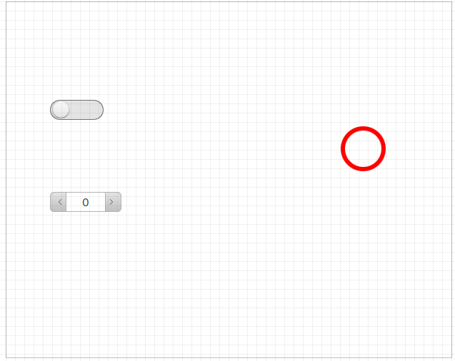
This is the final result:
Add graphical objects
We will add the objects in the first navigable panel, i.e. Page1 (type):
Double-click Page1 (type): the panel opens in the editor.
To add the LED, in Project right-click Page1 (type), then select New> Basic controls > LED LED: LED1 appears in Page1 (type) and in the objects editor.
To add the switch, in Project right-click Page1 (type), then select New > Basic controls > Switch Switch: Switch1 appears in Page1 (type) and in the objects editor.
To add the spin box, in Project right-click Page1 (type), then select New > Basic controls > Spin box Spin box: SpinBox1 appears in Page1 (type) and in the objects editor.
In the editor, drag the three objects to the desired position. Below is an example:
Associate the LED status with the switch status
To turn the LED on/off with a switch, we will insert a dynamic link between the activation states of the two objects:
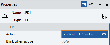
In the LED1 properties, click
 next to the Active property: the dynamic links window opens which displays all the project elements and their properties.
In the window, inside Switch1 select the Active variable and press Select: the value of the Active property of LED1 is the path to the switch property.
In this way, the LED status depends on the switch status. In this case, the two linked properties contain a value of the same type (Boolean). For this, a simple dynamic link is sufficient.
Find out more about dynamic links: Dynamic Links.
Associate the LED color with the spin-box value
In this phase, the link is between two properties that contain values of different types: number and color. For this, a converter has to be used, which transforms the input data into another type of data. Here we will use a Key-Value converter to transform the spin-box numerical data into data of color type for the LED.
Select the LED and click
next to its Color property, then click Advanced: the editor of the dynamic link for the Color property opens.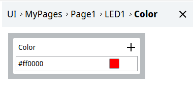
To add the converter, click
 > Key-Value converter: the block of the Key-value converter appears. DynamicLink Source indicates the input variable to the converter, which transforms it to supply its value to the Color property.
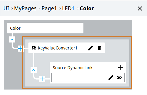
To set the converter input, in our case the spin-box value, in DynamicLink Source click
 , then in Spinbox1 select Value, then click Select.
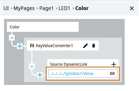
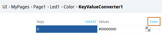
- To set the conversions to perform, in KeyValueConverter1 click
 : the conversion table appears in the object editor.
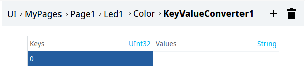
Each row defines a key/value pair: in this case Key is the spin-box value, Value is the LED color.
For the conversion, the correct data types must be set for Key and Value visible in the header; in particular Value must be of color type. To do it, in the Value column click String: a list with the most common data types appears.
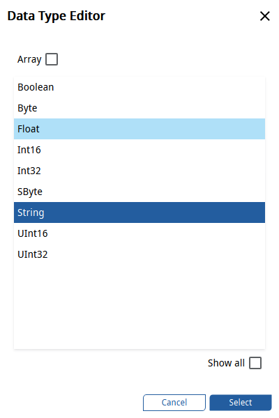
To display all the available data types, select Show All, then choose Color and click Select.
To change the color associated with the existing 0 key, click Pick in the related cell, select the color and click Select.
To set other key/value pairs, click
 and change the values. Below is an example:
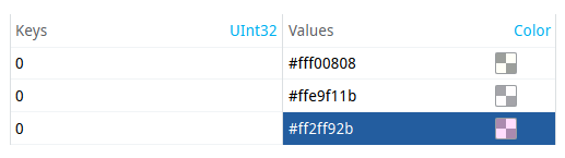
Find out more about the Key-Value converter: Key-Value converter.
To remember
When two variables of the same type are linked, a dynamic link is created.
When two variables of a different type are linked, it is necessary to set up one or more converters: then an advanced dynamic link is created.

