


Record and display alarms
Purpose of this module
In this module, we will create and configure a set of objects required to display and record alarms:
an object that reads a PLC variable related to a digital alarm
a widget to display and manage alarms in real time at runtime
a logger and a database to record alarms
a widget to display the history of events related to alarms
As there is no connection to a PLC, we will simulate the alarm activation via a switch or a button.
This is the final result:
Configure the digital Alarm object
We will configure the object that monitors the PLC Boolean variable for the alarm.
In Project, right-click the Alarms folder, then select New > Digital Alarm: DigitalAlarm1 appears in Alarms.
In the DigitalAlarm1 properties, click
 next to the Input value property and set a dynamic link with the Motor1Alarm alarm variable imported from the PLC.
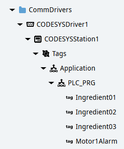
In the Message property, set the message to display at runtime on alarm activation, for example “Alarm on motor1”.
The Value status normal property is set to 0 by default: in this way, the alarm is activated when the value of the Motor1Alarm variable becomes 1. The other properties are set by default according to the typical use of digital alarms.
Configure the widget to display the alarms in real time
We will add and configure the widget in Page2 (type):
Click
 in the main toolbar: the template library opens.
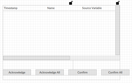
In Widgets, select the Alarm grid widget and drag it into Page2 (type): the AlarmGrid1 object appears in Page2 (type).
Close the template library.
In Project, double-click Page2 (type) to display the panel in the editor.
Click AlarmGrid1 and set its Horizontal alignment property to Stretch: in this way the widget adjusts to the width of the container.
Configure logger and database to store the alarms
From the template library we will add and configure an alarm logger, then we will configure a database in which to store the data recorded by the logger:
Click
in the main toolbar: the template library opens.In Misc, select the Event logger Alarms Event Logger object and drag it into the Loggers folder: the AlarmsEventLogger1 object appears in Loggers. This widget is designed to record all the alarms at runtime.
Close the template library.
To create a database, in Project, right-click DataStores, then select New > Embedded database Embedded Database: EmbeddedDatabase1 appears.
Rename EmbeddedDatabase1 to AlarmDB.
To set the database in which to store the alarms recorded by the logger, click AlarmsEventLogger1, and in its Database property set a dynamic link with AlarmDB.
Configure the widget to display the alarms history
We will add and configure the widget in Page3 (type):
Click
in the main toolbar: the template library opens.In Widgets, select the Alarm history grid widget and drag it into Page3 (type): the FilteredAlarmHistoryGrid1 object appears in Page3 (type).
Close the template library.
In Project, double-click Page3 (type) to display the panel in the editor.
Click FilteredAlarmHistoryGrid1 and set its Horizontal alignment property to Stretch: in this way the widget adjusts to the width of the container.
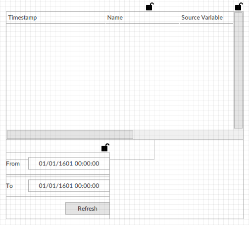
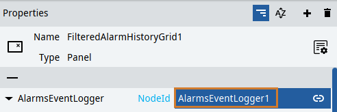
To display the data recorded by the logger in this widget, from Project drag AlarmsEventLogger1 onto the value of the AlarmsEventLogger property.
Configure the switch to simulate alarms
To simulate the activation of an alarm on the PLC, we will configure a Switch object with which to change the status of the Motor1Alarm variable.
In Project, double-click Page2 (type).
Right-click Page2 (type), then select New > Basic controls > Switch Switch: Switch1 appears in Page2 (type) and in the objects editor.
Drag the switch to the bottom part of the panel. Below is an example:
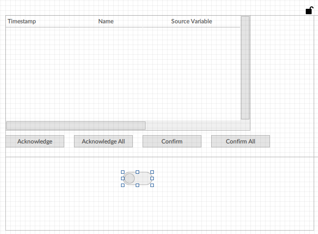
In the switch Active property, set a dynamic link with Motor1Alarm. In this way, the Boolean value of Motor1Alarm depends on the switch status.
Check the operation at runtime
The inserted widgets require space in width. Therefore, to display them properly at runtime, in Project click MainWindow (type) and set Width and Height to 1024 pixels and 560 pixels, respectively.
Click
 Emulator and wait for the runtime window to appear.
Click Page2, then to simulate the alarm activation on the PLC, change the switch status (on): the alarm grid displays the alarm data.
To acknowledge and confirm the alarm, select it in the list and click the buttons.
Change the switch status (off) to simulate the return of the alarm on the PLC: the alarm disappears from the list.
Click Page3: the grid displays the history of the alarm events.
To remember
Q Studio includes many templates to easily add and configure various features, such as the widgets used in this module. Before configuring an object or a set of objects from zero, it is therefore advisable to check whether suitable objects are already available in the template library. The library is periodically updated on the occasion of new software releases.

